Tolerances are where design intent meets manufacturing cost. Specify them too loosely and parts don't fit. Specify them too tightly and you pay for precision you don't need. This guide explains how machinists read tolerances and how to choose them sensibly.
What is a "standard" CNC tolerance?
For most machined metal parts, a linear tolerance of around ±0.1 mm is easily achievable and inexpensive. Many shops quote ±0.05 mm as a comfortable standard on modern machines. Below about ±0.02 mm, cost starts to rise because the part needs finishing passes, more careful fixturing, temperature control and more inspection.
ISO 2768 general tolerances
Rather than putting a tolerance on every dimension, most drawings reference a general tolerance standard in the title block. The most common is ISO 2768-1 for linear and angular dimensions. The "f" (fine) and "m" (medium) classes are used most:
| Nominal size (mm) | ISO 2768-f | ISO 2768-m |
|---|---|---|
| 0.5 – 3 | ±0.05 | ±0.1 |
| over 3 – 6 | ±0.05 | ±0.1 |
| over 6 – 30 | ±0.1 | ±0.2 |
| over 30 – 120 | ±0.15 | ±0.3 |
| over 120 – 400 | ±0.2 | ±0.5 |
ISO 2768-2 adds general geometric tolerances (classes H, K, L) for straightness, flatness, perpendicularity and similar. A note like "ISO 2768-mK" covers both parts.
Use the general tolerance for non-critical dimensions and apply specific tolerances only where function requires them.
GD&T: controlling form and position
Plus/minus tolerances control size, but they don't fully control shape and location. Geometric Dimensioning and Tolerancing (ASME Y14.5 or ISO GPS) adds controls such as:
- Flatness, roundness, cylindricity for form
- Perpendicularity, parallelism, angularity for orientation
- Position for hole patterns and features relative to datums
- Profile for complex surfaces
- Runout and concentricity for rotating parts
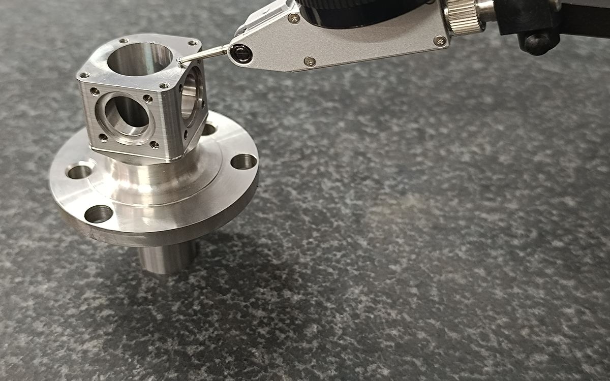
A well-chosen datum scheme tells the machinist how the part should be located, and tells the inspector how to measure it. Most of these characteristics are verified on a CMM.
When does ±0.001 mm matter?
Micron-level tolerances are real requirements on some features, such as bearing seats, precision bores for pins, valve spools, gauge components and certain aerospace and medical interfaces. They are achievable, but only with:
- Stable, temperature-controlled machining and inspection (steel grows about 11–12 µm per metre per °C)
- Rigid setups and finishing passes with sharp tooling
- Measurement equipment with resolution well below the tolerance
- Often a secondary process such as grinding, honing or lapping
Apply these tolerances to the one or two features that need them, not to the whole drawing.
How tolerances affect cost
As a rough guide, moving a feature from ±0.1 mm to ±0.025 mm can noticeably increase machining and inspection time for that feature, and going to a few microns may require an additional process. The biggest savings usually come from:
- Using a general tolerance standard for non-critical dimensions.
- Tolerancing only functional interfaces tightly.
- Using GD&T position instead of tight ± tolerances on hole coordinates.
- Avoiding tight tolerances on thin walls that will deflect during cutting.
Tolerance stack-up
When several parts are assembled, their tolerances add up. Before tightening every dimension, run a simple worst-case or statistical (RSS) stack-up on the critical assembly gap. Often only one or two dimensions drive the result.
Aeroedge International machines to tolerances as tight as ±0.001 mm on critical features, verified on a Mitutoyo CNC CMM in a temperature-controlled facility. If you're unsure which tolerances are worth paying for, send us your drawing and we'll flag any features that drive cost.